Custom mechanical keyboard: OS-specific custom RGB lighting with QMK
My old Corsair keyboard has been struggling recently. It has some weird issues,
either in hardware or firmware, that cause it to sometimes go crazy and
randomly “press” the wrong keys, forcing me to pull out my backup keyboard until
the lunacy1 passes. On top of that, managing it requires Corsair’s bloated,
Windows-only iCUE software or a reverse-engineered alternative like
ckb-next, which isn’t fun for a Linux user like me, and even with
ckb-next, the customization is limited.
So I figured I’d get a new keyboard. I have a few simple requirements:
- It should be a 100% keyboard because I use the numpad quite a bit for number entry, e.g. to manage my personal finances;
- It should have a backlight since I often use my computer at night in relative darkness, and while I can touch type just fine, being able to see the keyboard is nice;
- It should have tactile mechanical switches, but not the obnoxious clicky ones. For reference, my old keyboard has Cherry MX browns, which I liked; and
- It should have properly programmable and customizable firmware. QMK is the popular option, so I searched for keyboards supporting that, and failing that, at least keyboards with proper first-party Linux support.
As it turned out, I couldn’t find any prebuilt mechanical keyboards that ticked all the options and were in stock, so I figured I might just get into the custom mechanical keyboard scene and build my own. Thus began a journey that saw immense frustration and nerd-sniping…
Picking the parts
So I looked up the parts I would need for the custom mechanical keyboard and decided to get the following items:
- A Monsgeek M5 keyboard frame, which is a reasonably affordable metal keyboard frame (since I didn’t want to “downgrade” to plastic) with QMK firmware support. It helped that it was on sale on AliExpress and I had some coupons. It also has these “south-facing” LEDs, which sounded like they should be sufficient as a backlight for my keyboard. To make sure, I decided to do some quick research, and apparently “south-facing” is “better” for some obscure keycap compatibility reasons2, so I just went with it. Spoiler: this was a huge mistake.
- A bunch of Akko Lavender Purple switches, which were tactile, had good reviews, and were also heavily on sale on AliExpress. I was originally going to just get Cherry MX browns, but then I heard Cherry switches are no longer the best these days.
- Some shine through keycaps so I can benefit from the keyboard backlight.
- Some Krytox 250G0 lube that’s very popular among mechanical keyboard people.
- A keycap and switch puller.
Once all the parts arrived, I assembled the keyboard. One thing I didn’t realize was that I had to take apart the entire Monsgeek M5 frame just to install the stabilizers3, which were of course not installed just in case you want to modify them. So I had a lot of fun pulling all the switches back out before disassembling the entire frame. And then I had the pleasure of struggling to unscrew some overly tight screws on the PCB…
After much struggle and repetition4, I finally assembled the keyboard. To my shock and horror, the backlight doesn’t penetrate the keys! How could this be? I thought the keycaps had to be fake, but when I pulled them out and tried to shine a flashlight through, they lit up just fine. That was when I found that south-facing LEDs were to blame, and in fact, the keys lit up just fine when I installed them upside down. The only alternative is to get side-printed keycaps, which look ridiculous and I am really not in the mood to replace all the keycaps.
So basically, while trying to build a custom keyboard that meets all my requirements, I failed to meet requirement #2. This was disappointing.
Key takeaway: South-facing LEDs attempt to fix a minor keycap compatibility, at the cost of completely destroying the LEDs’ ability to act as backlight. The cure is much worse than the disease. Please don’t make the same mistake.
Building QMK firmware
Regardless, I have a keyboard now. While I was forced to resort to touch typing in the dark on what are effectively blank keycaps, I might as well make the best out of the situation by reprogramming the keyboard to my tastes, and that meant getting started on QMK.
The way they often tell people to get started on custom QMK firmware is to use the QMK configurator, but this is actually fairly underpowered in customizability. You can’t even flash the firmware on Linux that easily, since QMK Toolbox—the tool they normally tell you to use to flash the firmware generated by the configurator—doesn’t work on Linux! You basically need to install the whole development environment to flash firmware on Linux, so I just did that, abandoning the configurator.
It was pretty simple, actually. You just run pip install qmk and run qmk
setup and it’ll magically get things sorted. Then I just ran the following
commands to make it remember which keyboard I had, and then created my custom
layout:
qmk config user.keyboard=monsgeek/m5
qmk config user.keymap=quantum5
qmk new-keymap
Side note: QMK strongly suggests you name the keymaps by your GitHub username for easy version control, so that’s what I did.
Then I just edited
~/qmk_firmware/keyboards/monsgeek/m5/keymaps/quantum5/keymap.c to customize my
keyboard layout, before running qmk flash to flash it. It’s that simple.
I also took a peek at the repository, and it really didn’t seem that hard to understand as long as you have a tiny bit of embedded C development experience. Luckily enough, I already programmed a similar microcontroller as a university project, so I felt perfectly comfortable.
Custom RGB effects
Since I could program the keyboard to do whatever I wanted now, I naturally got nerd-sniped by the possibilities. I was reminded of this fancy RGB effect that Corsair’s iCUE could do back when I still used it and decided to replicate it in QMK for fun. Essentially, there’s a constant RGB background colour, but whenever you press a key, a coloured ripple radiates out from the key, and multiple ripples can overlap and blend together. With QMK, the entire thing can be done in firmware, without requiring something like iCUE running in the background. Of course, this is completely pointless, but that’s what makes it fun.
As it turns out, QMK already has a similar class of effects called “multisplash”, though none of the effects worked the way I wanted. Basically, the effects disable the backlight and only light up when a key is pressed, further defeating the purpose of the already ruined backlight. The regular multisplash variant splashes a full spectrum, while the “solid multisplash” effect only splashes one colour.
I wanted to have a background colour and a ripple of a random colour distinct from the background radiate out, so I just wrote my own effect, stealing some code from the multisplash effects. It was actually surprisingly easy.
First, since I wanted each keystroke to have a ripple of constant colour, I
needed to modify QMK’s key tracker to have a random value fixed for each
keystroke, since I didn’t want to implement my own tracking. So I added a new
RGB_MATRIX_KEYREACTIVE_RND_STROKE feature to QMK’s RGB matrix component, which
is basically this trivial patch:
diff --git a/quantum/rgb_matrix/rgb_matrix.c b/quantum/rgb_matrix/rgb_matrix.c
index 70175f9d50..6b4674c007 100644
--- a/quantum/rgb_matrix/rgb_matrix.c
+++ b/quantum/rgb_matrix/rgb_matrix.c
@@ -179,15 +179,22 @@ void rgb_matrix_handle_key_event(uint8_t row, uint8_t col, bool pressed) {
         memcpy(&last_hit_buffer.y[0], &last_hit_buffer.y[led_count], LED_HITS_TO_REMEMBER - led_count);
         memcpy(&last_hit_buffer.tick[0], &last_hit_buffer.tick[led_count], (LED_HITS_TO_REMEMBER - led_count) * 2); // 16 bit
         memcpy(&last_hit_buffer.index[0], &last_hit_buffer.index[led_count], LED_HITS_TO_REMEMBER - led_count);
+#ifdef RGB_MATRIX_KEYREACTIVE_RND_STROKE
+        memcpy(&last_hit_buffer.rnd[0], &last_hit_buffer.rnd[led_count], LED_HITS_TO_REMEMBER - led_count);
+#endif // RGB_MATRIX_KEYREACTIVE_RND_STROKE
         last_hit_buffer.count = LED_HITS_TO_REMEMBER - led_count;
     }

     for (uint8_t i = 0; i < led_count; i++) {
         uint8_t index                = last_hit_buffer.count;
+
         last_hit_buffer.x[index]     = g_led_config.point[led[i]].x;
         last_hit_buffer.y[index]     = g_led_config.point[led[i]].y;
         last_hit_buffer.index[index] = led[i];
         last_hit_buffer.tick[index]  = 0;
+#ifdef RGB_MATRIX_KEYREACTIVE_RND_STROKE
+        last_hit_buffer.rnd[index]   = random8();
+#endif // RGB_MATRIX_KEYREACTIVE_RND_STROKE
         last_hit_buffer.count++;
     }
 #endif // RGB_MATRIX_KEYREACTIVE_ENABLED
diff --git a/quantum/rgb_matrix/rgb_matrix_types.h b/quantum/rgb_matrix/rgb_matrix_types.h
index 0a3fd7cc0d..30453722af 100644
--- a/quantum/rgb_matrix/rgb_matrix_types.h
+++ b/quantum/rgb_matrix/rgb_matrix_types.h
@@ -37,6 +37,9 @@ typedef struct PACKED {
     uint8_t  y[LED_HITS_TO_REMEMBER];
     uint8_t  index[LED_HITS_TO_REMEMBER];
     uint16_t tick[LED_HITS_TO_REMEMBER];
+#ifdef RGB_MATRIX_KEYREACTIVE_RND_STROKE
+    uint8_t  rnd[LED_HITS_TO_REMEMBER];
+#endif // RGB_MATRIX_KEYREACTIVE_RND_STROKE
 } last_hit_t;
 #endif // RGB_MATRIX_KEYREACTIVE_ENABLED
For the actual effect, I just created users/quantum5/rgb_matrix_user.inc with
the following C code:
RGB_MATRIX_EFFECT(splash_on_backlight)

#ifndef RGB_MATRIX_KEYREACTIVE_RND_STROKE
#error "RGB_MATRIX_KEYREACTIVE_RND_STROKE required to use splash_on_backlight"
#endif

#ifdef RGB_MATRIX_CUSTOM_EFFECT_IMPLS
static bool splash_on_backlight(effect_params_t *params) {
    RGB_MATRIX_USE_LIMITS(led_min, led_max);

    uint8_t count = g_last_hit_tracker.count;
    for (uint8_t i = led_min; i < led_max; i++) {
        RGB_MATRIX_TEST_LED_FLAGS();
        HSV hsv = rgb_matrix_config.hsv;

        int16_t hx = 0, hy = 0;
        uint8_t cnt = 0;
        for (uint8_t j = 0; j < count; j++) {
            int16_t  dx   = g_led_config.point[i].x - g_last_hit_tracker.x[j];
            int16_t  dy   = g_led_config.point[i].y - g_last_hit_tracker.y[j];
            uint8_t  dist = sqrt16(dx * dx + dy * dy);
            uint16_t tick = scale16by8(g_last_hit_tracker.tick[j], qadd8(rgb_matrix_config.speed, 1));
            uint16_t str  = tick - dist;
            if (str < 45) {
                uint8_t hue = hsv.h + scale8(g_last_hit_tracker.rnd[j], 192) + 32;
                hx += cos16(hue << 8) >> 4;
                hy += sin16(hue << 8) >> 4;
                ++cnt;
            }
        }

        if (cnt) {
            hsv.h = atan2_8(hy, hx);

            hx = (hx / cnt) >> 3;
            hy = (hy / cnt) >> 3;
            hsv.s = scale8(sqrt16(hx * hx + hy * hy), hsv.s);
        }
        RGB rgb = rgb_matrix_hsv_to_rgb(hsv);
        rgb_matrix_set_color(i, rgb.r, rgb.g, rgb.b);
    }
    return rgb_matrix_check_finished_leds(led_max);
}
#endif
Basically, for every LED, we go through all the recently tracked keys and find
the distance of the LED from the originating key. Subtracting that by the
elapsed time multiplied by some speed constant, we obtain how recently the
ripple reached every LED. If it was within the arbitrarily chosen value of 45,
then it decides that the ripple is currently there, and uses the randomly chosen
colour of the key.
However, there’s quite a bit of math required to accomplish two things:
- To make sure the ripple colour is sufficiently distinct from the background colour; and
- To properly blend two ripples together.
To understand how this all works, we must first understand the HSV colour space.
HSV colour space
For RGB lighting effects, it’s paradoxically often easier to think of colours in the HSV colour space instead of the “normal” RGB colour space. The HSV colour space looks like this:
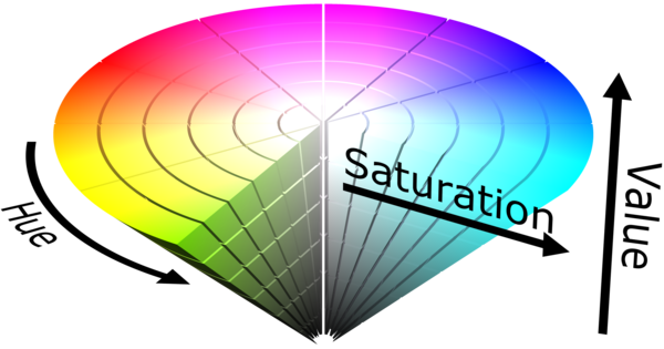
The HSV cone (source)

Since for LED lighting, the value is just the brightness, we’ll only think in hue and saturation, resulting in the circular chart on the right. For the rest of this article, we’ll only think in hue and saturation, and refer to the chart as the hue–saturation wheel, or HS wheel.
Let’s use standard mathematical convention, assigning colour on the right an angle of 0°, with angles increasing counter-clockwise. So 0° is red, 60° is yellow, 120° is green, 180° is cyan, 240° is blue, 300° is magenta, and 360° is red once again. This angle is called the hue angle.
In QMK, this hue angle is normalized to between 0 and 255, so 0 is red, 128 is cyan, and 255 is almost red again.
Distinct colours
To ensure that the ripple is distinct, I make sure that the 90° slice of the HS wheel centred on the backlight hue can’t be selected through this line of code:
uint8_t hue = hsv.h + scale8(g_last_hit_tracker.rnd[j], 192) + 32;
Effectively, we scale the random byte we generated to between 0 and 192 (270°), then add it to the backlight hue and add 32 (45°) more. This ensures the hue differs from the backlight by at least 45°.
Blending HSV
When there are two ripples, they have to blend together somehow. You might think the answer is just averaging the hue angles, but that’s wrong. For example, red and cyan are 0° and 180° respectively, so the average is 90°, which is a greenish-yellow colour. However, when you actually combine the colours, the result should be white. So this is clearly wrong.
As it turns out, the way to blend colours is by averaging them together on the HS wheel. Geometrically, the resulting colour is the centre of mass.
However, such geometric calculations are difficult to compute, so we instead convert it to algebra by modelling each colour as a complex number, which makes this surprisingly elegant to express.
Let’s assume we are trying to blend colours into the colour . We can express each colour using Euler’s equation as follows:
Then, the resulting colour is just the mean of all the complex numbers:
We note that and and define the following variables:
Then, we can compute and using the standard formulæ for complex number magnitude and argument.
A non-complex number interpretation would involve using polar coordinates instead for colours, adding them in Cartesian space, and converting them back to polar coordinates. In this case, the hue is the angle and the saturation is the length of the vector. The derivation is similar and results in an identical outcome, just less elegant.
In C, this is implemented as follows:
int16_t hx = 0, hy = 0;
uint8_t cnt = 0;
for (uint8_t j = 0; j < count; j++) {
    ...
    uint8_t hue = ...;
    hx += cos16(hue << 8) >> 4;
    hy += sin16(hue << 8) >> 4;
    ++cnt;
}

if (cnt) {
    hsv.h = atan2_8(hy, hx);

    hx = (hx / cnt) >> 3;
    hy = (hy / cnt) >> 3;
    hsv.s = scale8(sqrt16(hx * hx + hy * hy), hsv.s);
}
We start by assuming the hues are pure, i.e. with maximum saturation, then
adding up the values in Cartesian space. Note that QMK’s helper functions
cos16 and sin16 return the values scaled to the range
instead to avoid floating point arithmetic5. We >> 4 to divide it by 16 to
avoid overflow when adding up multiple colours.
Then, if we were blending at least one colour, we use atan2_8, which converts
Cartesian coordinates into the polar angle, obtaining the hue. For the
saturation, we scale hx and hy down by the number of colours, and divide by
8 with >> 3 to normalize it into the range. This allows us to
use the Pythagorean theorem and compute hx * hx + hy * hy in the range , which we use sqrt16 to convert to a number between . We
then scale the result to the configured saturation, which is the old value of
hsv.s.
Enabling the effect
To get QMK to build the custom effect, you need these lines in the keymap’s
rules.mk:
RGB_MATRIX_ENABLE = yes
RGB_MATRIX_CUSTOM_USER = yes
OS detection
Since I have to use a MacBook at work, I would like the keyboard to detect that it’s connected to a macOS machine and activate the Mac-specific layout. To make it obvious the Mac layout is active, I’d like a different backlight colour as well.
This is surprisingly easy to do, since QMK comes with an OS detection
module. To enable it, put this line in rules.mk:
OS_DETECTION_ENABLE = yes
Then, it’s a matter of listening to the process_detected_host_os_user
callback in the keymap.c:
static void update_background_led(os_variant_t os) {
    HSV hsv = rgb_matrix_get_hsv();

    switch (os) {
        case OS_MACOS:
        case OS_IOS:
            rgb_matrix_sethsv_noeeprom(43, hsv.s, hsv.v); // yellow
            break;
        case OS_WINDOWS:
            rgb_matrix_sethsv_noeeprom(170, hsv.s, hsv.v); // blue
            break;
        case OS_LINUX:
            rgb_matrix_sethsv_noeeprom(0, hsv.s, hsv.v); // red
            break;
        case OS_UNSURE:
            rgb_matrix_sethsv_noeeprom(85, hsv.s, hsv.v); // green
            break;
    }
}

bool process_detected_host_os_user(os_variant_t detected_os) {
    rgb_matrix_enable_noeeprom();
    rgb_matrix_mode(RGB_MATRIX_CUSTOM_splash_on_backlight);

    update_background_led(detected_os);

    switch (detected_os) {
        case OS_MACOS:
        case OS_IOS:
            default_layer_set(1 << MAC_B);
            break;
        default:
    }

    return true;
}

layer_state_t default_layer_state_set_user(layer_state_t state) {
    if (state & (1 << MAC_B)) {
        update_background_led(OS_MACOS);
    } else {
        os_variant_t os = detected_host_os();
        switch (os) {
            case OS_MACOS:
            case OS_IOS:
                update_background_led(OS_UNSURE);
                break;
            default:
                update_background_led(os);
                break;
        }
    }

    return state;
}
For fun, I gave every OS a different hue, with Linux as red, macOS as yellow,
Windows as blue, and any unknown OS as green. I also made it so that changing
the default layer through hotkeys will also change the backlight colour through
the default_layer_state_set_user callback. Note that the default layer is
changed through DF(MAC_B) and DF(WIN_B) keys.
Once the OS is detected, it configures the RGB effect, but without writing anything to the EEPROM since the colours are determined at startup time.
What’s next?
Honestly, given that I did all this stuff within the first day screwing around with QMK, I am quite horrified by how deep this rabbit hole goes. I already have the idea to convert the platform-specific keyboard layouts that allow me to type various accented characters into additional QMK logic that uses various escape sequences to type Unicode characters directly… Let’s hope this doesn’t end up sucking all my time.
Notes
-
Fun fact: the word lunacy is derived from lunatic, which is derived from the Latin word for moon luna, under the belief that such intermittent insanity is caused by the changes in the moon. I can’t explain why the Corsair keyboard is acting up, so I’ll just blame the phase of the moon instead. ↩
-
So apparently “north-facing” keyboard designs will cause the poorly designed Cherry profile keycaps to bottom out prematurely, and the solution was to flip the switches around and put the LEDs in the “south” side of the key. And apparently, south-facing LEDs are more brilliant or something because they directly face the user.
What these mechanical keyboard enthusiasts don’t tell you is the cost of this design: the LEDs illuminate the bottom half of the keycaps and you can’t find keycaps with legends on the bottom half, making the RGB completely useless as a backlight. Apparently, Cherry profile keycaps are much more important to them and they dismiss RGB as a “useless gamer feature,” preferring to just touch type in the dark… ↩
-
Basically, these are the things that connect the sides of longer keys on the keyboard together (e.g. the spacebar), ensuring that the whole key goes down together even when you apply force to one side only. ↩
-
I thought building a custom mechanical keyboard would be as fun as building a custom PC, but no, everything has to be done 100 times. ↩
-
Floating point is surprisingly expensive on microcontrollers, and the CPU in the keyboard doesn’t have an FPU either. ↩