DIY a Stratum 1 NTP Server with a Serial Port
These days, it seems like everyone is posting about turning Raspberry Pis into a stratum 1 NTP server by hooking up a cheap GPS module, most often the GT-U7 u-blox 7 clone with a PPS (pulse-per-second) signal output, whose rising edge indicates exactly the start of a second.
While this seems like a cool idea, it suffers from one flaw—while the Raspberry Pi itself almost certainly has very accurate time, getting accurate time to the rest of the network would be problematic. This is because the Ethernet adapter on Raspberry Pis before the Pi 4 was hooked up via USB, and the polling nature of USB introduces jitter, preventing the accurate signal from reaching the rest of the network. Unfortunately, I only have a Raspberry Pi 3 model B in my possession, which suffers from the problem.
Now, I could have gotten a Raspberry Pi 4, but those aren’t priced sanely at the
moment and it would be just an exercise in copying. Instead, I looked at the
various alternatives. The traditional way of doing this kind of thing involves
hooking up a GPS receiver into a serial port, which generates an
interrupt. If the PPS signal is delivered to the DCD (data carrier
detect) signal (as described in RFC 2783), then the in-tree Linux
driver pps_ldisc is able to do the timestamping in kernel mode for
the highest possible accuracy.
I found out that my server’s X570 motherboard came with a serial port
header (labelled COM). This meant that I could buy some fancy GPS receiver
with a serial port and hook it up. Unfortunately, those aren’t priced sanely
either, so I decided to build my own with the GT-U7 module and a driver module
for RS-232 (the common serial port standard).
This was late last year. I ordered the components on AliExpress and they all arrived in January, so I finally started this project.
The GT-U7 module

The GT-U7 module can be used in several ways. It can be powered via USB and also shows up as a USB serial port, from which one can communicate with the module with standard NMEA 0183 sentences. It can also be powered via the pins and has a UART interface, which is what people use to communicate with Raspberry Pis.
Now, the GT-U7 module has 5 pins:
-
VCC: hooked up to the VBUS pin of the USB port and also the input of the RT9193-33GB voltage regulator. Note that the actual chip expects 3.3 V, which is what the regulator outputs. -
GND: the ground pin, which is also hooked up to the GND pin of the USB port. -
TXD: the transmit pin of the UART, sending data out of the module. This sends the data out at 3.3 V. -
RXD: the receive pin of the UART, receiving commands to the module. Note that this pin expects 3.3 V and anything higher may fry the chip. -
PPS: the module pulses this pin once a second to 3.3 V. The rising edge of this pulse is supposed to indicate the exact start of a TAI/UTC/GPS1 second—at least as far as the module could determine. It is possible to configure the module to make this the falling edge instead, which is useful if the signal has to go through an inverter.
Now, UART and PPS can’t be hooked to serial ports due to voltage issues, since serial ports expect RS-232 voltage levels, which use +3 V to +15 V to indicate 0 or asserting a control pin, and -15 V to -3 V to indicate a 1 or deasserting a control pin. This requires another circuit to drive the RS-232 serial port.
The RS-232 driver module

For this purpose, I decided to get an RS-232 serial driver (specifically this one2) based on the SP3232E chip (datasheet). It has six pins on one side to interface with any TTL (transistor–transistor logic) serial interface and a DB-9 female serial interface on the other side that can be connected to a serial port on a PC. In the language of RS-232, a female connector means a DCE (data circuit-terminating equipment), and a male connector is a DTE (data terminal equipment). This means that the PC acts as a DTE in this case, and this module acts as a DCE. Here’s the pinout for the module:
-
VCC: 3 V to 5.5 V input to power the SP3232E chip. -
GND: the ground pin. -
RXD: the receive pin, outputting data transmitted by the PC to the serial port. The output voltage is equal to VCC. -
TXD: the transmit pin, whose value is stepped up to RS-232 levels before being sent to the PC. -
CTS: despite the label, this is not the “clear to send” signal. Looking at the RS-232 standard, this seems to be hooked up to the RTS (request to send) instead, which should be an input pin on a DCE. I confirmed this is indeed the case after looking at the schematic and probing the traces with a multimeter. -
RTS: this is actually the CTS (clear to send) signal, an output pin from the UART’s perspective.
One thing to note is that the SP3232E chip has two sets of RX/TX pairs. Recall that 0 V on the TTL side yields a positive voltage on the RS-232 side, and 5 V on the TTL side yields a negative RS-232 voltage. However, “CTS” and “RTS” on the module are control signals, so a positive voltage on the RS-232 side would be asserting them. This effectively means that they are active low. There will be consequences of this later.
Connecting the GT-U7 to the RS-232 driver
The astute among you may see a problem if I want to power the GT-U7 via USB, which uses 5 V. The GT-U7 module has a 3.3 V UART, so hooking the VCC from the GT-U7 to the SP3232 will generate a 5 V output on the RX pin, potentially frying the GPS receiver. Instead, I need to send 3.3 V to VCC of SP3232.

Naturally, I could use an alternate power source, but USB is such a convenient way of powering the chip and it would really suck to have to use something else. Now, the GT-U7 has an RT9193-33GB voltage regulator to generate 3.3 V, so it must be possible to tap into it.
So with my trusty multimeter, I probed all the pins around the chip until I found the 3.3 V output. I soldered a wire to it to plug it into the VCC on the SP3232 module. Then, the GND, TXD, RXD pins on the GT-U7 can be connected to pins of the same name on the SP3232 module. I also connected the PPS pin to the “RTS” pin (really CTS).
Since I was soldering wires already, I opted to solder wires directly to the pins on the GT-U7 instead of soldering on a header first. Here’s the result:

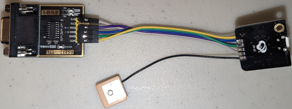
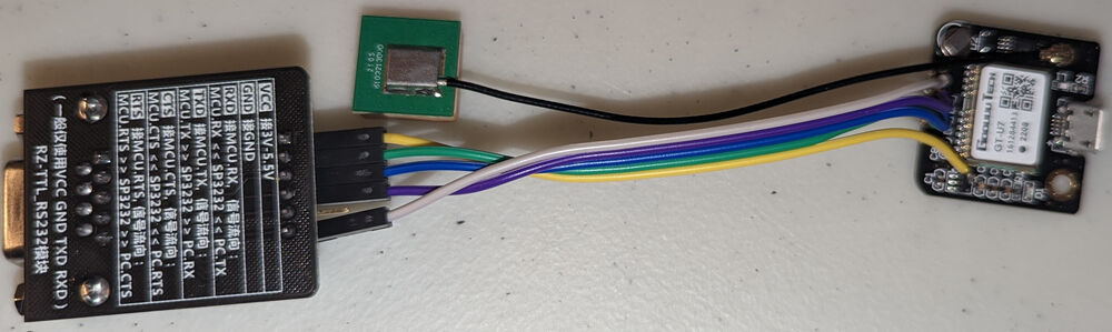
Colour key: yellow for 3.3 V, green for ground, blue for RX, purple for TX, and white for PPS.
Powering it on
Once the modules are connected, I simply used a DB-9 male-to-female cable to
connect the RS-232 driver to the serial port on my server. Then I plugged the
GT-U7 into a USB power brick. Surprisingly, it worked, and I was able to get
NMEA sentences by running tio -b 9600 /dev/ttyS0:
$ tio -b 9600 /dev/ttyS0
[tio 03:16:31] tio v1.32
[tio 03:16:31] Press ctrl-t q to quit
[tio 03:16:31] Connected
$GPTXT,01,01,02,u-blox ag - www.u-blox.com*50
$GPTXT,01,01,02,HW  UBX-G70xx   00070000 FF7FFFFFo*69
$GPTXT,01,01,02,ROM CORE 1.00 (59842) Jun 27 2012 17:43:52*59
$GPTXT,01,01,02,PROTVER 14.00*1E
$GPTXT,01,01,02,ANTSUPERV=AC SD PDoS SR*20
$GPTXT,01,01,02,ANTSTATUS=DONTKNOW*33
$GPTXT,01,01,02,LLC FFFFFFFF-FFFFFFFF-FFFFFFFF-FFFFFFFF-FFFFFFFD*2C
$GPRMC,031637.49,V,,,,,,,240123,,,N*76
$GPVTG,,,,,,,,,N*30
$GPGGA,031637.49,,,,,0,00,99.99,,,,,,*6B
$GPGSA,A,1,,,,,,,,,,,,,99.99,99.99,99.99*30
...
Unfortunately, there was a problem—my DB-9 cable was too short. If I put the GPS module anywhere reachable by the cable from my server, I could not get a location fix, which means no accurate time either. I was able to confirm the GT-U7 worked by connecting it to my laptop and putting it next to the window. This meant I had to get a longer serial cable.
Not to be deterred, I ordered a 7.5 m cable and ran it from my PC to the
window.3 Lo and behold, I was able to get a fix and see it in gpsmon
/dev/ttyS0.
Getting a PPS signal
The next thing to do is to get the PPS signal working. To do this, I used the
ppscheck utility, which on Debian is in the gpsd package.
$ sudo ppscheck /dev/ttyS0
# Seconds  nanoSecs   Signals
 1674519707.093109125 TIOCM_CTS
 1674519707.993113023
 1674519708.093109417 TIOCM_CTS
 1674519708.993110629
 1674519709.093123693 TIOCM_CTS
...
What does this mean? Well, it seems like the PPS signal appears on the CTS pin 93 ms after the start of a second according to the clock in my server, and it clears 993 ms after the start of a second. This is not right.
First of all, by default, the GT-U7’s PPS signal has a duty cycle of 10%, meaning that it should be high for 100 ms. Instead, what I am seeing here is the signal being up for 900 ms, meaning it’s inverted. Remember earlier that the CTS signal was active low due to the SP3232E chip? Well, this is a problem.
Fortunately, the GT-U7 module can be configured in u-blox’s u-center
program (download u-center, not u-center 2). This application has one
of the most confusing UIs I’ve seen. Essentially, follow these steps:
- Install u-center and open it.
- Plug in the GT-U7 module via USB and wait for Windows to install the drivers. It should show up as a serial port.
- Go to the Receiver menu and select Connection, then select COMx
where
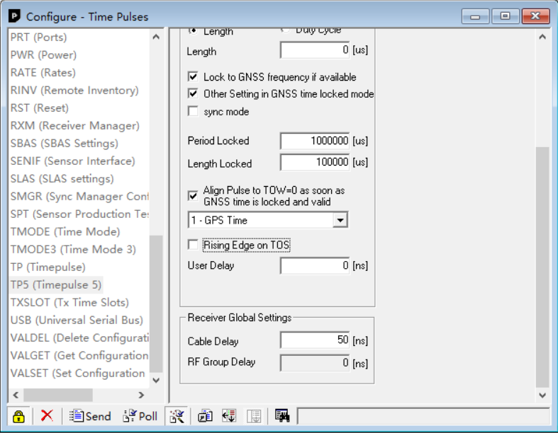
xis whatever number your serial port shows up as. - Go to the View menu and select Configuration view, then select TP5 on
the left. Press Poll on the bottom of the window to fetch the current
settings, then scroll down and uncheck Rising Edge on TOS, then press
Send:
 The GT-U7 module should now mark the start of the second on the falling edge
of the PPS signal. However, this change is lost upon reboot.
The GT-U7 module should now mark the start of the second on the falling edge
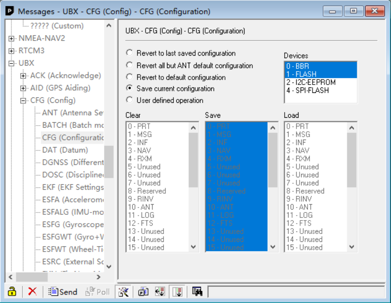
of the PPS signal. However, this change is lost upon reboot. - To make this change persist, go to the View menu again and select Messages
view, then on the left side, navigate to UBX, CFG, CFG, then select
the Save current configuration option to 0 - BBR and 1 - Flash. Press
Send:
Now let’s plug in the serial cable and try again:
$ sudo ppscheck /dev/ttyS0
# Seconds  nanoSecs   Signals
 1674521280.993574692 TIOCM_CTS
 1674521281.093455443
 1674521281.993595705 TIOCM_CTS
 1674521282.093563432
 1674521282.993439722 TIOCM_CTS
 1674521283.093438782
 ...
Much better. The clock on my server was probably around 6.4 ms off due to the poor NTP servers I was using.
However, there is still one problem—the kernel can’t timestamp the CTS signal, only the DCD signal. This means that the timings will have more jitter, and that’s obviously not acceptable. Naturally, the next step is to bring the signal onto the DCD pin.
Put PPS on DCD

Doing some probing, I found that the DCD pin on the RS-232 driver is not connected to anything. Therefore, I should be able to short it to the CTS pin. Essentially, you want pin 1 of the DB-9 connector to be shorted to pin 8. I simply soldered a wire connecting the two pins:

After this modification, ppscheck sees the TIOCM_CD signal:
$ sudo ppscheck /dev/ttyS0
# Seconds  nanoSecs   Signals
 1674530110.993574692 TIOCM_CD TIOCM_CTS
 1674530111.093455443
 1674530111.993595705 TIOCM_CD TIOCM_CTS
 1674530112.093455443
 1674530112.993439722 TIOCM_CD TIOCM_CTS
 1674530113.093438782
 ...
Setting up the GPS daemon
With the PPS signal ready, it’s a simple matter of getting gpsd to use it.
Since it’s already installed, we just need to configure it. Here’s my
/etc/default/gpsd:
# Devices gpsd should collect from at boot time.
# They need to be read/writeable, either by user gpsd or the group dialout.
DEVICES="/dev/ttyS0"

# Other options you want to pass to gpsd
GPSD_OPTIONS="-n"

# Automatically hot add/remove USB GPS devices via gpsdctl
USBAUTO="true"
It should then be a matter of systemctl restart gpsd.service for our changes
to take effect. gpsd should take care of creating the PPS device /dev/pps0
for you. You can verify it by running ppstest (from pps-tools):
$ sudo ppstest /dev/pps0
trying PPS source "/dev/pps0"
found PPS source "/dev/pps0"
ok, found 1 source(s), now start fetching data...
source 0 - assert 1674536843.005214951, sequence: 412 - clear  1674536842.105210840, sequence: 411
source 0 - assert 1674536843.005214951, sequence: 412 - clear  1674536843.105219197, sequence: 412
source 0 - assert 1674536844.005212934, sequence: 413 - clear  1674536843.105219197, sequence: 412
source 0 - assert 1674536844.005212934, sequence: 413 - clear  1674536844.105226089, sequence: 413
If /dev/pps0 is not created, you can run the following commands to create it:
sudo modprobe pps-ldisc
sudo ldattach PPS /dev/ttyS0
sudo systemctl restart gpsd.service
Setting up NTP
The next step is to set up ntpd. If you are using chrony, please see the
gpsd documentation.
First, install the ntpd package if you haven’t already. Then, you need to
configure NTP to use the gpsd output. I simply added the following lines to
/etc/ntpd.conf:
# GPS Serial data reference (NTP0)
server 127.127.28.0
fudge 127.127.28.0 time1 0.126 refid GPS

# GPS PPS reference (NTP1)
server 127.127.28.1 prefer
fudge 127.127.28.1 refid PPS
The time1 0.126 value may need to be adjusted for your setup due to various
GPS delays, but that’s roughly the value I find that works decently, though
there is a fair amount of jitter. For more details and better tuning, see the
gpsd documentation.
After restarting ntpd (sudo systemctl restart ntpd), you can run ntpq -pn
and see something like:
     remote           refid      st t when poll reach   delay   offset  jitter
==============================================================================
+127.127.28.0    .GPS.            0 l    2   64  377    0.000   -6.759   2.009
*127.127.28.1    .PPS.            0 l    1   64  377    0.000   +0.276   1.845
 0.ca.pool.ntp.o .POOL.          16 p    -   64    0    0.000   +0.000   0.000
 1.ca.pool.ntp.o .POOL.          16 p    -   64    0    0.000   +0.000   0.000
 2.ca.pool.ntp.o .POOL.          16 p    -   64    0    0.000   +0.000   0.000
 3.ca.pool.ntp.o .POOL.          16 p    -   64    0    0.000   +0.000   0.000
...
At this point, ntpd is working and we now have a stratum 1 NTP server. Of
course, that offset and jitter value for the PPS source isn’t that impressive.
That’s because it needs some time to settle. For example, over night, it would
settle to something like:
     remote           refid      st t when poll reach   delay   offset  jitter
==============================================================================
+127.127.28.0    .GPS.            0 l   12   64  377    0.000   -6.545   0.134
*127.127.28.1    .PPS.            0 l   11   64  377    0.000   +0.008   0.006
...
8 μs offset and 6 μs of jitter, that’s more like it.
What’s next?
As far as NTP is concerned, we are basically done. However, we could in theory do better.
PTP (Precision Time Protocol) is supposed to be able to deliver clock accuracy in the sub-microsecond range, unlike NTP’s millisecond accuracy. Theoretically, my ConnectX-3s support this:
$ sudo ethtool -T enp5s0
Time stamping parameters for enp5s0:
Capabilities:
  hardware-transmit
  software-transmit
  hardware-receive
  software-receive
  software-system-clock
  hardware-raw-clock
PTP Hardware Clock: 1
Hardware Transmit Timestamp Modes:
  off
  on
Hardware Receive Filter Modes:
  none
  all
Note the PTP Hardware Clock: 1 and hardware-transmit, hardware-receive,
and hardware-raw-clock abilities. I may try this one day and write about it
here.
Update: I wrote about PTP 2 days later.
Notes
-
While these standards all differ from each other, both UTC and GPS time are defined as integer offsets of TAI so their seconds all start at the same time. For more details, see my post on time standards and note that GPS is 17 seconds behind TAI. ↩
-
As you shall see, this particular RS-232 driver board has an additional pin that could be used to connect the PPS signal. Most other drivers I’ve seen support amplifying an additional signal, but that requires tapping into one of those tiny pins and I have no desire to solder onto something that tiny. ↩
-
This probably introduced on the order of 40 ns of latency due to the extra cable length, but oh well. ↩